Understanding the basics of Graphical projections.
Blog post description.
3/8/20264 min read
GRAPHICAL PROJECTION
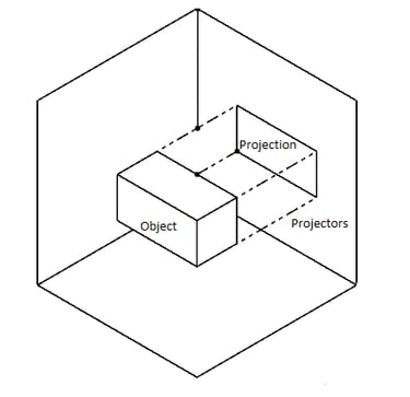
Graphical Projections is a method of representing a 3D object on a 2D Surface.
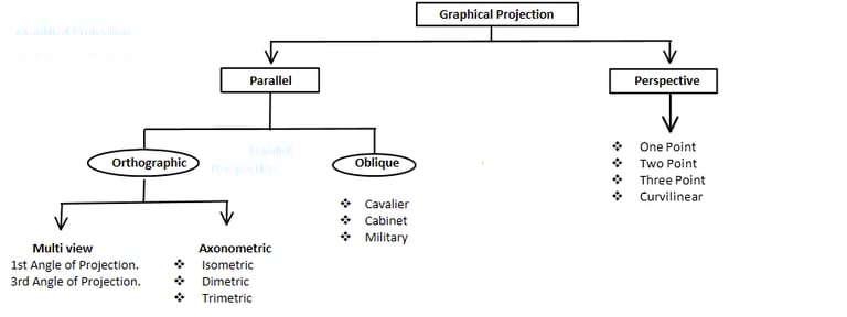
Classification of Graphical Projection.
Parallel Projection: In Parallel Projection all Projectors are Parallel to each other. It gives accurate dimension and it used in engineering drawings.
Orthographic Projection: Projectors are perpendicular (90°) to Projection plane.
Multi view: Since single cannot describe the object Accurately, so we use multiple views of object to understand its true shape, dimensions and hidden features. And it subcategorized into 1st Angle of Projection and 3rd Angle of Projection.
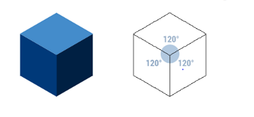
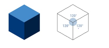
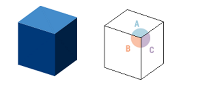
Axonometric View: In axonometric Projection the Object is tilted with respect to Projection Plane, to visualize three sides of object at once.
Isometric Projection: Three axis are 120° to each other.
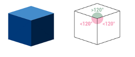
Dimetric Projection: Two axis are in same angle and 3rd axis is in different angle.
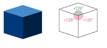
Trimetric Projection: All three axis are in different angles.
Oblique Projection: In this Projection the front view is drawn with true size and depth is drawn at angle to show third dimension.
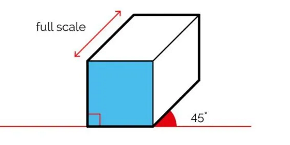
Cavalier: In this Projection front and side view is drawn to its true size and side view is drawn with an angle of 45°.
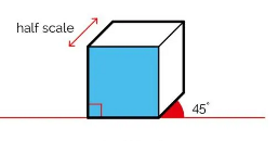
Cabinet: In Cabinet projection front view is drawn to its true size and side view is drawn at an angle of 45° with half of its true dimension.
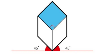
military: In military Projection both length and width side are drawn to its true size at an angle of 45° to horizontal axis.
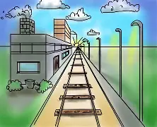
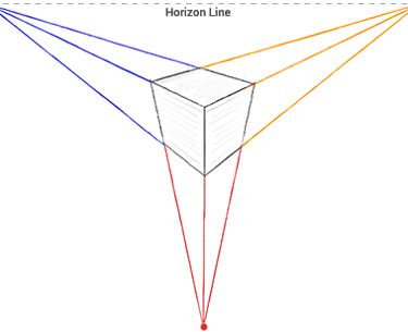
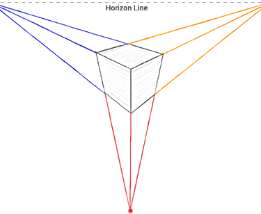
Prospective Projection: In Perspective Projection all Projectors converge to one point. This projection gives more realistic view like human vision and used in architecture design.
One Point: View tend to converge at one point.
Two Point: View tends to converge at two points.
Three Point: View tends to converge at three points.
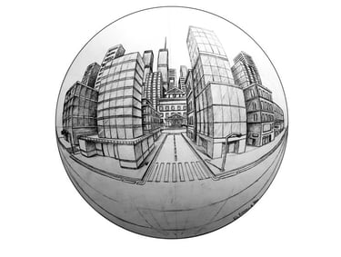
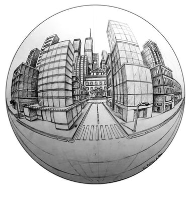
Curvilinear: In curvilinear Projection straight line become curved to show a wide viewing angle.
Angle of Projection:
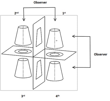
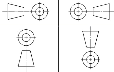
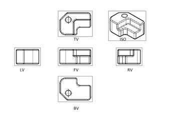
1st Angle of Projection: In 1st angle of Projection the Object is placed in 1st Quadrant and it is in between the Observer and Plane of Projection.
Top view will be projected on horizontal plane and right-side view will project on Vertical Plane.
Horizontal plane will rotate 90° clockwise thus to get 1st angle of Projection.
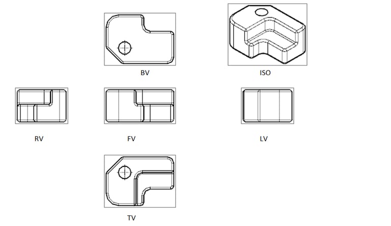
1st angle of Projection can be represented as blow four ways.
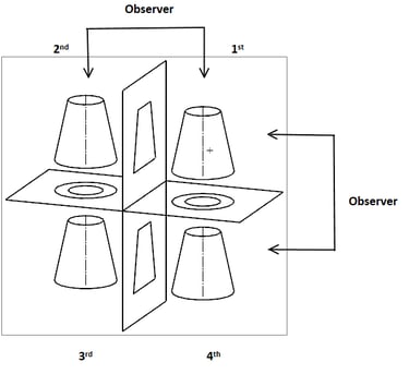
2nd Angle of Projection: In 2nd angle of Projection the Object is placed in 2nd Quadrant and Plane of Projection is placed between the object and observer.
Top view will be projected on horizontal plane and right-side view will project on Vertical Plane.
Horizontal plane will rotate 90° clockwise thus to get 2nd angle of Projection, but both Horizontal plane and Vertical Plane co inside each other, we will not use 2nd angle of Projection
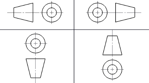
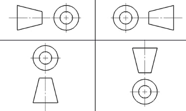
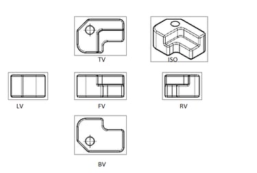
3rd Angle of projection: In 3rd angle of Projection the Plane of Projection is placed between the object and observer. Top view will be projected on horizontal plane and right-side view will project on Vertical Plane.
Horizontal plane will rotate 90° clockwise thus to get 3rd angle of Projection.
3rd angle of Projection can be represented as blow four ways.
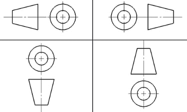
4th Angle of Projection: In 4th angle of Projection the Object is placed in 4th Quadrant and it is placed in between the Observer and Plane of Projection.
Top view will be projected on horizontal plane and right-side view will project on Vertical Plane.
Horizontal plane will rotate 90° clockwise thus to get 4th angle of Projection. Since Horizontal plane and vertical plane coincide each other, we will not use 4th angle of projection.