Basics of engineering drawing,
Basics of engineering drawing.
3/13/20266 min read
What is engineering Drawing?
Engineering drawing is a universal language of communication between a Designer, Manufacturer and Inspector.
It describes all the necessary requirement of a product, such as shape, size, tolerance material, assembly sequence etc. of a part accurately.
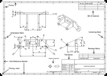
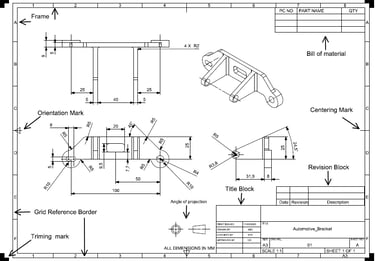
Drawing sheet layout.
Trimming Mark: L Shaped thick line of size 10 X 0.5 mm located at outside of all four corners of border line, it helps to cutting of excess sheet to achieve standard sheet size.
Margin: It is the space between the sheet edge to border line used for binding, and it is 20 mm left side and 10 mm at top, bottom and right side.
Border line: It is an outer rectangular line just inside the trimming mark, which defines the margin for sheet to provide the space for binging.
Frame line: it is an inner rectangular line forms the boundary for actual drawing area.
Grid reference border: it is used to divide the drawing sheet into zones, to easy identification of drawing views or details for large drawing sheets. The top and bottom horizontal direction is marked with numbers, and vertical direction left and right sides are marked with alphabets as shown in above image.
Example: Right side view on above image is located at D6 zone.
Orientation mark: it indicates the correct direction to view the drawing sheet
Types of Mechanical engineering drawing.
Part (Detail) drawing:
It provides all the necessary information such as dimensions, tolerance, material, and surface finish to manufacture a single component.
Production Drawing:
It is part drawing with production details, such as surface finish, heat treatment, also notes for manufacturing.
Assembly Drawing:
It shows assembling sequence of individual parts into a machine.
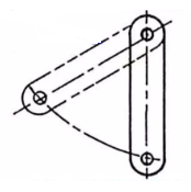
Exploded view Drawing:
Display separated parts in a 3D assembly to show how they fit together.
Installation Drawing:
it is guides the technicians to installation or erection the machine at the site.
Contents of Drawing Sheet Layout:
Views of the part
Dimensions & tolerance of part
Title block
Revision Block
Bill of materials
Views of Part:
Part is displayed in orthographic projection i.e. either 1st angle or 3rd angle of projection.
It usually contains FV, TV, BV, LV, RV, & ISO. it also contains, detail view, section view.
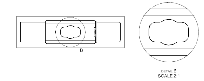
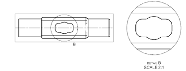
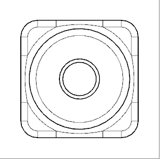
Detail view:
It gives the enlarged view of small and complicated portion of drawing; it helps in understanding the accurate dimensions of small portion clearly.
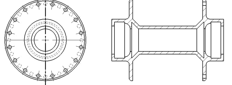
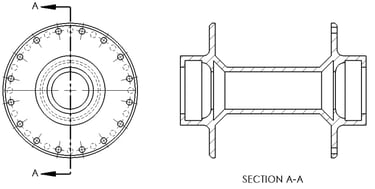
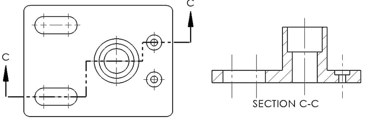
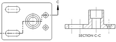
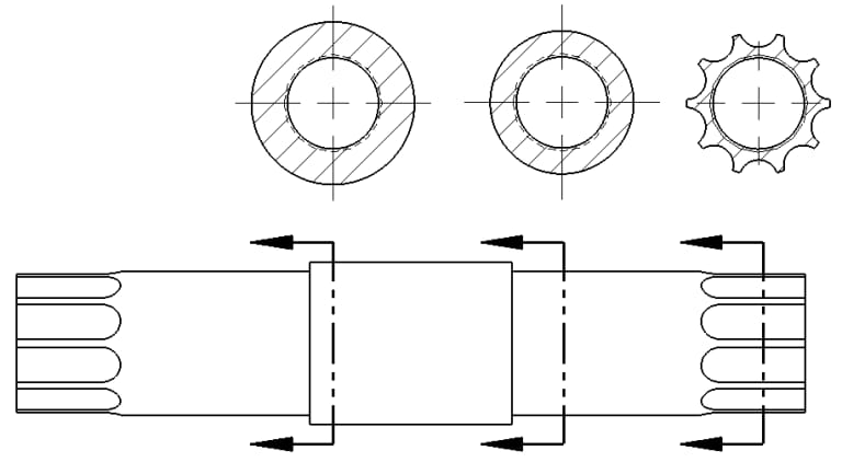
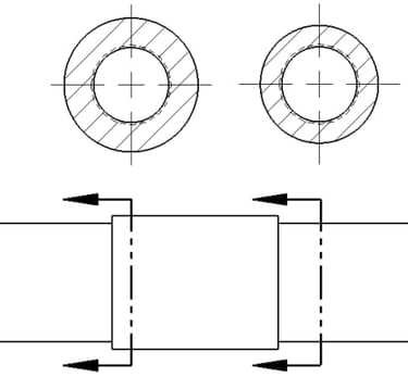
Sectional view:
Sectional view shows the internal features of a part by cutting and removing front portion of part by imaginary cutting plane.
Types of sectional view:
Full section: Entire front half of a Part is removed by cutting through the center of part to revel the internal feature of the part.
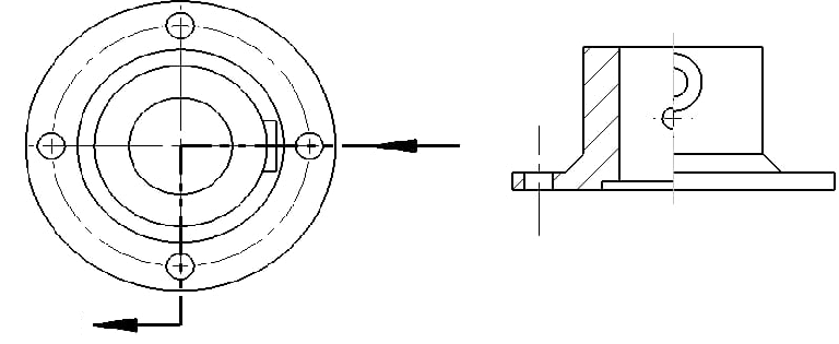
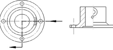
Half section: The quarter of the part is cut through two perpendicular planes passing through the center is removed, the remainder is called a half section. And it is used for symmetrical objects.
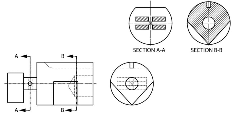
Offset Section: In offset section view the cutting plane is offset to pass through the important features that are not in straight line.
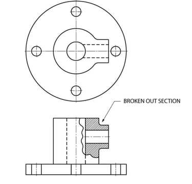
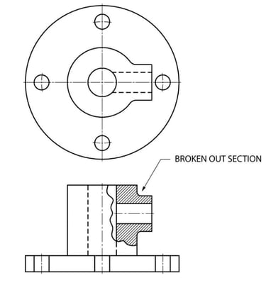
Breakout section: A small portion of object is cut to revel the internal feature of a part.
Revolved section view: A revolved section view is a cross-section obtained by cutting the object and rotating the section 90° so it can be drawn within the main view of the object.
Removed section is a cross-section of an object that is taken at a cutting plane and placed away from the main view instead of being drawn directly on it.
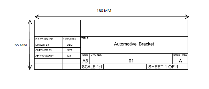
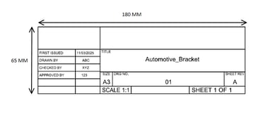
Title Block:
The title block is located at the bottom right corner of drawing sheet for both sheets positioned horizontally or vertically.
Typical title block size varies from 170-180 mm X 65 mm.
Title block size can vary because of Company standards and drawing sheet size.
title block, providing the following information:
(1) Title of the drawing (2) Sheet number (3) Scale (4) Sheet size (5) Symbol, denoting the method of projection (6) Name of the organization (7) Initials of staff drawn, checked and approved.
Revision Block:
Revision block table contains all the modification done on the Part or drawing, from the date of its first issue, it helps in tracking design change and drawing history.
Bill Of Material:
it is a table which lists the quantity of all the components or parts required to manufacture or assemble a product.
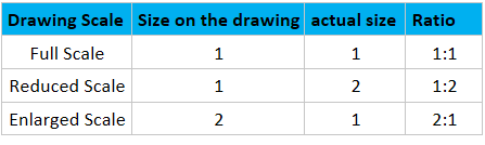
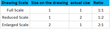
Drawing Scale:
It is the ratio between the size of a part in drawing to its actual size.
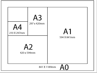
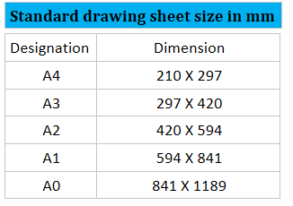
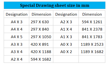
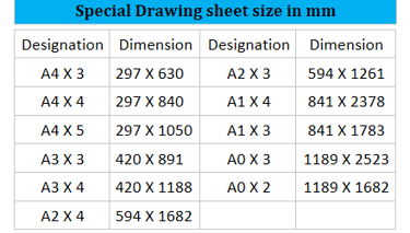
Drawing Sheet size:
The basic principles involved in arriving at the sizes of drawing sheets are:
(a) X: Y = 1: √2, (b) XY = 1 where X and Y are the sides of the sheet.
size A0 having a surface area of 1 m²
The successive format sizes are obtained either by halving along the length or doubling along the width, the areas being in the ratio 1:2
Different types of lines used in engineering drawing:
Visible line:
A thick continuous line used to represent visible edges, and part boundary.
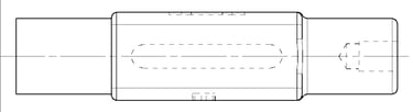
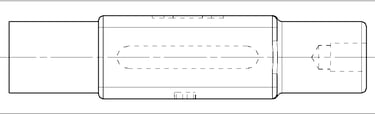
Hidden line:
A thin dashed lines used to show the edges and features which are not visible from current view.
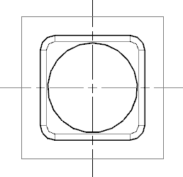
Center line:
A thin chain of long dash - short dash used to represent Center of arc, circle symmetric part.
Dimension line:
Thick continuous line with arrowhead used to indicate measurement of a feature.
Extension line:
A thick continuous line extended from feature to show limits of dimension lines.
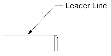
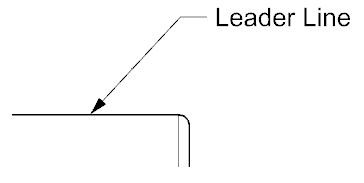
Leader line:
A thin inclined line with an arrowhead or dot to use to connect notes, symbols, dimensions to a specific feature.
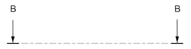
Cutting plane line:
A thick chain line with arrowhead used to cut the object where section view is required.
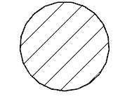
Section line:
A thin parallel line at an angle of 45° used to show the surface exposed after the cut.
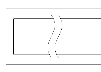
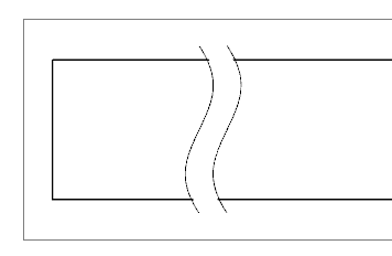
Break line:
A wavy or zigzag line used to indicate certain portion of part is removed to shorten the drawing.
Phantom line:
A thin chain of long chain - short chain - short chain used to show position of moving parts.